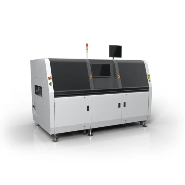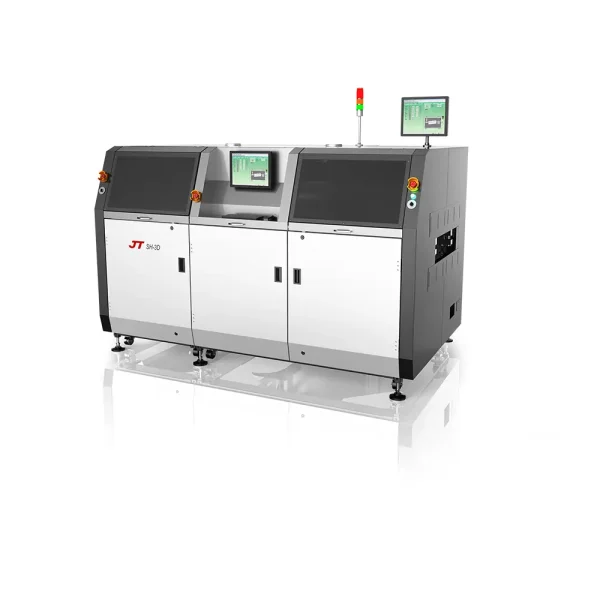
SMD reflow, short for Surface Mount Device reflow soldering, is a widely – used technique in electronics manufacturing. It enables the connection of surface – mounted components to printed circuit boards (PCBs).
The process starts with applying solder paste on PCB pads, which contains a mixture of solder alloy and flux. Then, a pick – and – place machine positions components onto the solder – pasted pads. Next, in a reflow oven, the PCB goes through multiple temperature – controlled zones. First, in the preheat zone, it warms up gradually to avoid thermal shock. Then in the reflow zone, the solder paste melts, allowing components to bond with the pads. Finally, in the cooling zone, the solder solidifies, forming strong and reliable electrical and mechanical connections. This precise soldering method ensures high – quality and efficient production of electronic products.
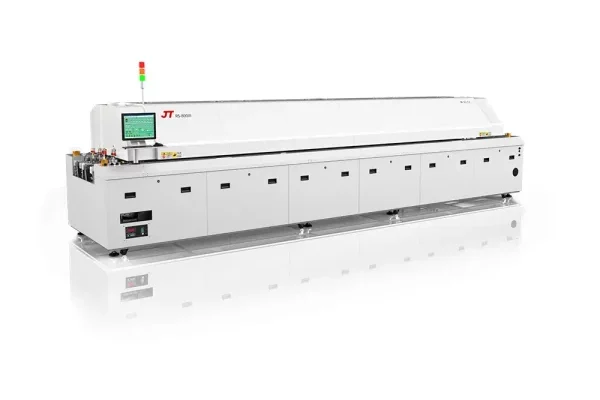
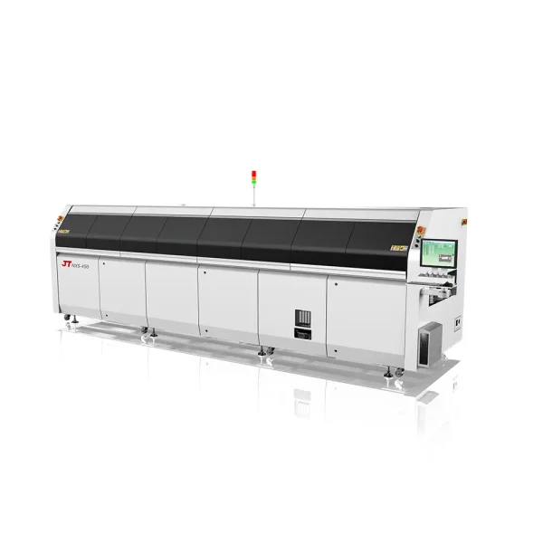
| MODEL | RS-600III/RS-600III-N |
| GENERAL | |
| Outside Dimension(L*W*H) | 4190 x 1430 x 1530mm |
| Weight | Approx. 1850KG/1950KG |
| Number Of Heating Zones | Up 6 / Bottom 6 |
| Length Of Heating Zones | 2295mm |
| Number Of Cooling Zones | Up 1 / Bottom 1 (Cool Air Conversion) |
| Exhaust Volume | 10 m³ / min x 2 (Exhausts) |
| Control System | |
| Electric Supply Required | 3 phase, 380V 50/60Hz (Optional: 3 phase, 400V/480V 50/60Hz ) |
| Electric Power Required | 48KW / 51KW |
| Power For Warm Up | 24KW / 26KW |
| Power Consumption | 6.5KW / 7KW |
| Warming Time | Approx. 20 minute |
| Temp. Setting Range | Room Temp. — 300℃ |
| Temperature Control Method | PID Close Loop Control + SSR Driving |
| Temperature Control Precision | ± 1.0℃ |
| Temperature Deviation on PCB | ± 1.5℃ (by JT Board Test Standard) |
| Commutated Element | Aluminium Alloy Plate |
| Data Storage | Various prameters and status are storable (80GB) |
| Abnormal Alarm | Abnormal Temperature (Extra-high / Extra-low Temp.) |
| Board Dropped Alarm | Tower Light: Yellow–Warming; Green-Normal; Red-Abnormal |
| Conveyor System | |
| Rail Structure | Subsection Integrated Type (Option : Subsection Separate Control) |
| Max.Width Of PCB | 400mm (OPTION :460mm) |
| Range Of Rail Width/Adjustment | 50~400mm / Motorized |
| Components Clearance | PCB Top 30mm/ Bottom 25mm |
| Converyor Direction | L→R (Option: R→L) |
| Fixed Rail Side | Front Rail Fixed (Option:Rear Rail Fixed) |
| PCB Transmission Agent | Air-Reflow =Chain + Mesh , ( N2-Reflow = Chain only and Mesh optional) |
| Converyor Height | 900±20mm |
| Converyor Speed Range | 300~2000mm/min |
| Lubrication Auto-Afflux | Standard |
| Cooling System | |
| Cooling Method | Standard:Forced-Air Type |
Notes: D:Dual rails,Fixed mode is optional,the max width of PCB is 250*250mm;N:Nitrogen;L:the max width of PCB is 610mm
The above contents are subiect to change without further notice.