
SMT reflow, short for Surface Mount Technology reflow soldering, is a key process in electronics manufacturing. It’s used to attach surface – mount components to printed circuit boards (PCBs). First, solder paste, a mixture of solder alloy and flux, is printed onto the PCB pads. Then, components are precisely placed on the paste by a pick – and – place machine.
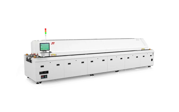
The PCB is then sent through a reflow oven, which has multiple temperature – controlled zones. In the pre – heat zone, the board is gradually heated to around 150 – 180 °C to activate the flux and prevent thermal shock. Next, in the soak zone (180 – 200 °C), the temperature is kept stable, allowing the flux to fully work. In the reflow zone, the temperature peaks at 230 – 250 °C, melting the solder to form strong joints. Finally, in the cooling zone, the board cools down, solidifying the solder joints. This process ensures reliable electrical and mechanical connections between components and PCBs.
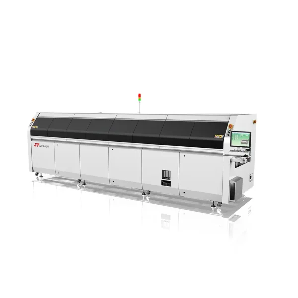
| MODEL | RS-600III/RS-600III-N |
| GENERAL | |
| Outside Dimension(L*W*H) | 4190 x 1430 x 1530mm |
| Weight | Approx. 1850KG/1950KG |
| Number Of Heating Zones | Up 6 / Bottom 6 |
| Length Of Heating Zones | 2295mm |
| Number Of Cooling Zones | Up 1 / Bottom 1 (Cool Air Conversion) |
| Exhaust Volume | 10 m³ / min x 2 (Exhausts) |
| Control System | |
| Electric Supply Required | 3 phase, 380V 50/60Hz (Optional: 3 phase, 400V/480V 50/60Hz ) |
| Electric Power Required | 48KW / 51KW |
| Power For Warm Up | 24KW / 26KW |
| Power Consumption | 6.5KW / 7KW |
| Warming Time | Approx. 20 minute |
| Temp. Setting Range | Room Temp. — 300℃ |
| Temperature Control Method | PID Close Loop Control + SSR Driving |
| Temperature Control Precision | ± 1.0℃ |
| Temperature Deviation on PCB | ± 1.5℃ (by JT Board Test Standard) |
| Commutated Element | Aluminium Alloy Plate |
| Data Storage | Various prameters and status are storable (80GB) |
| Abnormal Alarm | Abnormal Temperature (Extra-high / Extra-low Temp.) |
| Board Dropped Alarm | Tower Light: Yellow–Warming; Green-Normal; Red-Abnormal |
| Conveyor System | |
| Rail Structure | Subsection Integrated Type (Option : Subsection Separate Control) |
| Max.Width Of PCB | 400mm (OPTION :460mm) |
| Range Of Rail Width/Adjustment | 50~400mm / Motorized |
| Components Clearance | PCB Top 30mm/ Bottom 25mm |
| Converyor Direction | L→R (Option: R→L) |
| Fixed Rail Side | Front Rail Fixed (Option:Rear Rail Fixed) |
| PCB Transmission Agent | Air-Reflow =Chain + Mesh , ( N2-Reflow = Chain only and Mesh optional) |
| Converyor Height | 900±20mm |
| Converyor Speed Range | 300~2000mm/min |
| Lubrication Auto-Afflux | Standard |
| Cooling System | |
| Cooling Method | Standard:Forced-Air Type |
Notes: D:Dual rails,Fixed mode is optional,the max width of PCB is 250*250mm;N:Nitrogen;L:the max width of PCB is 610mm
The above contents are subiect to change without further notice.