Without reflow machines, electronics manufacturing would be an arduous task if not an outright impossibility. These tools, which are often called reflow ovens, help to solder or attach surface-mount electronic components to Printed Circuit Boards (PCBs). Unless the reflow machine is at its optimum, the connection it will create among the components will be shaky and unreliable, affecting the overall structural integrity of the manufactured electronics.
Thankfully, there are a couple of ways to ensure these critical tools deliver optimum results. These include
- Even Heat Distribution of the Reflow Machine
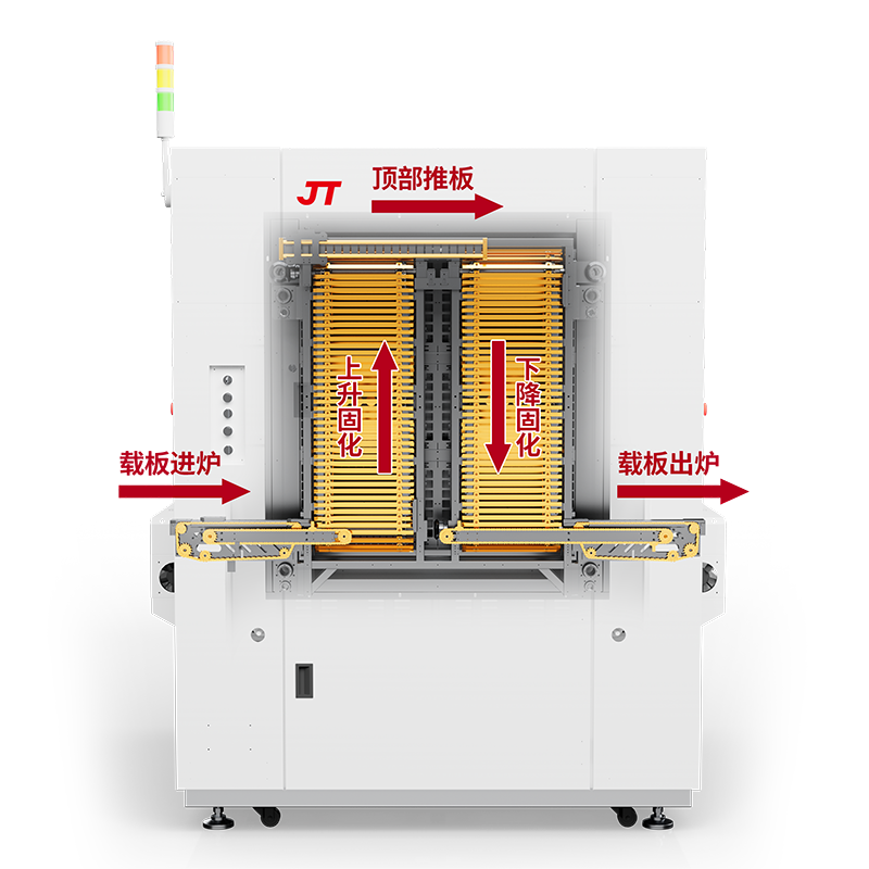
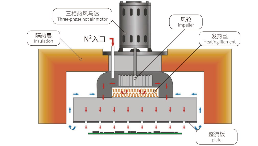
If heat is not evenly distributed during the reflow soldering process, it can cause thermal stress on components or incomplete solder joints. Using convection heating where hot hair is circulated the PCB is the way to ensure uniform heat that will reduce the possibility of hot and cold spots.
- Temperature Profile Optimization
There are four stages or zones in the temperature profile of a reflow machine. These include preheating, soaking, reflow, and cooling. At each of these stages, it’s imperative to guard against slow ramp-ups or rapid temperature rise to prevent insufficient flux activation or component damage. Electronic manufacturers can fine-tune the temperature profile of their reflow machines using advanced profiling techniques and tools such as thermocouples.
- Improved Cooling Process
In reflow soldering, cooling is just as important as the heating process. Regardless of assembly size or alloy characteristics of the electronics, gradual cooling is better than rapid cooling, which can cause cracks and other deformities. The advised cooling rate is between 1.5 and 60C. and it guarantees a fine-grained microstructure joint that maintains the mechanical integrity of the components.
Common Side Defects with Reflow Machines
Sometimes, things don’t go as envisaged when using reflow machines, leading to certain defects. Some of these defects and how to address or prevent them are briefly discussed.
- Solder Bridges: – This happens when there is excess solder forming a conductive path between adjacent pads, resulting in short circuits. It can be prevented by optimizing the stencil design so it doesn’t deposit too much solder. In addition, if a uniform heat distribution is ensured during soldering and an adequate reflow profile is maintained, solder pooling and bridging won’t happen.
- Solder Cracks: – Heat stress is the primary culprit in solder cracks and it happens with uncontrolled heating or cooling during the reflow process. Cracks are a threat to the electrical and mechanical integrity of soldier joints and, therefore, must be prevented. A way around this is to use solder pastes with adequate flux composition and maintain a steady heating and cooling rate.
- Component Displacement: – This phenomenon is also known as the Manhattan effect or tombstoning. It happens when uneven heating or surface tension differences cause components to move during the reflow process. The only way to minimize this is to ensure even heat distribution and keep the reflow profile optimized.
Conclusion
Using a reflow machine for soldering involves paying close attention to multiple factors, most of which have been briefly touched on above. At JT, we have the experience, equipment, and manpower to deliver cutting-edge SMT products for your electronics. We are the best company to talk to for your reflow machine and SMT production needs because we’ve been doing this for over 20 years and have several patents in our coffers.