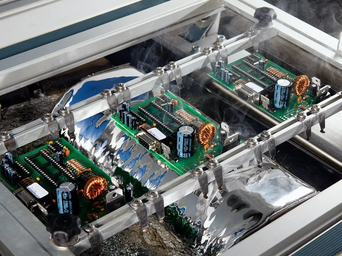

One of the toughest challenges in PCBA is Mixed Technology: placing a tiny 0201 capacitor next to a massive screw terminal or shield.
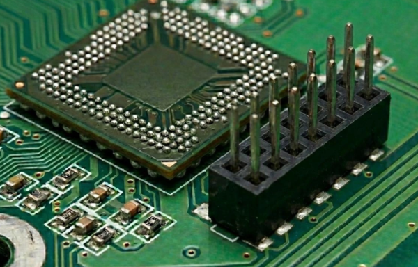
Mixed SMT Assembly and Thermal Mass Imbalance
Mixed Technology (or Mixed Assembly) is defined as the integration of components with extreme variances in thermal mass on a single PCB. This typically involves placing microscopic passives (like 0201 or 01005 chips) adjacent to high-mass components such as:
● Large BGAs: Which often have integrated metal heat spreaders (lids).
● Shielded Inductors: Which contain dense ferrite or iron cores that act as heat sinks.
● Through-Hole Connectors: Which are increasingly reflowed using “Pin-in-Paste” techniques rather than wave soldering.
While standard SMT lines optimize for throughput speed, mixed technology lines must optimize for thermal equilibrium. The fundamental engineering challenge is that a 0201 resistor heats up almost instantly, while a large shielded inductor lags by 20-30 seconds. If the profile isn’t tuned perfectly, the resistor will overheat and oxidize before the inductor’s solder paste even reaches liquidus.
The Thermal Lag Problem and Execution
The 0201 has almost zero thermal mass; it heats up instantly. Conversely, a heavy BGA or shielded inductor acts as a heat sink, lagging behind significantly. If you ramp up too fast (Linear Profile), the 0201 flows while the terminal is still solid. If you simply raise the temperature, the 0201 might “cook,” exhausting its flux before the heavy part is ready.
How it is Performed (Ramp–Soak–Reflow): Mixed SMT soldering is performed by implementing a specific “Extended Soak” strategy. Process engineers configure the oven’s Zone 2 to maintain a steady temperature plateau (typically 150℃ – 175℃ ) for an extended window of 90 to 120 seconds.
● The Mechanism: The heavier components are still continuing to absorb heat in this “thermal pause” while the small components have already risen in temperature and are just waiting (stopped).
● The Result: The thermal differential (ΔT) collapses. When the board finally enters the Reflow Zone, both heavy and light components cross the liquidus line simultaneously, ensuring uniform wetting without thermal damage.
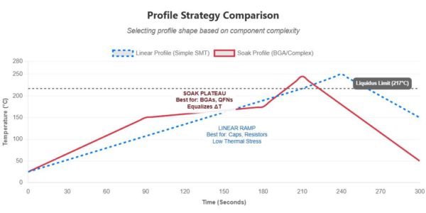
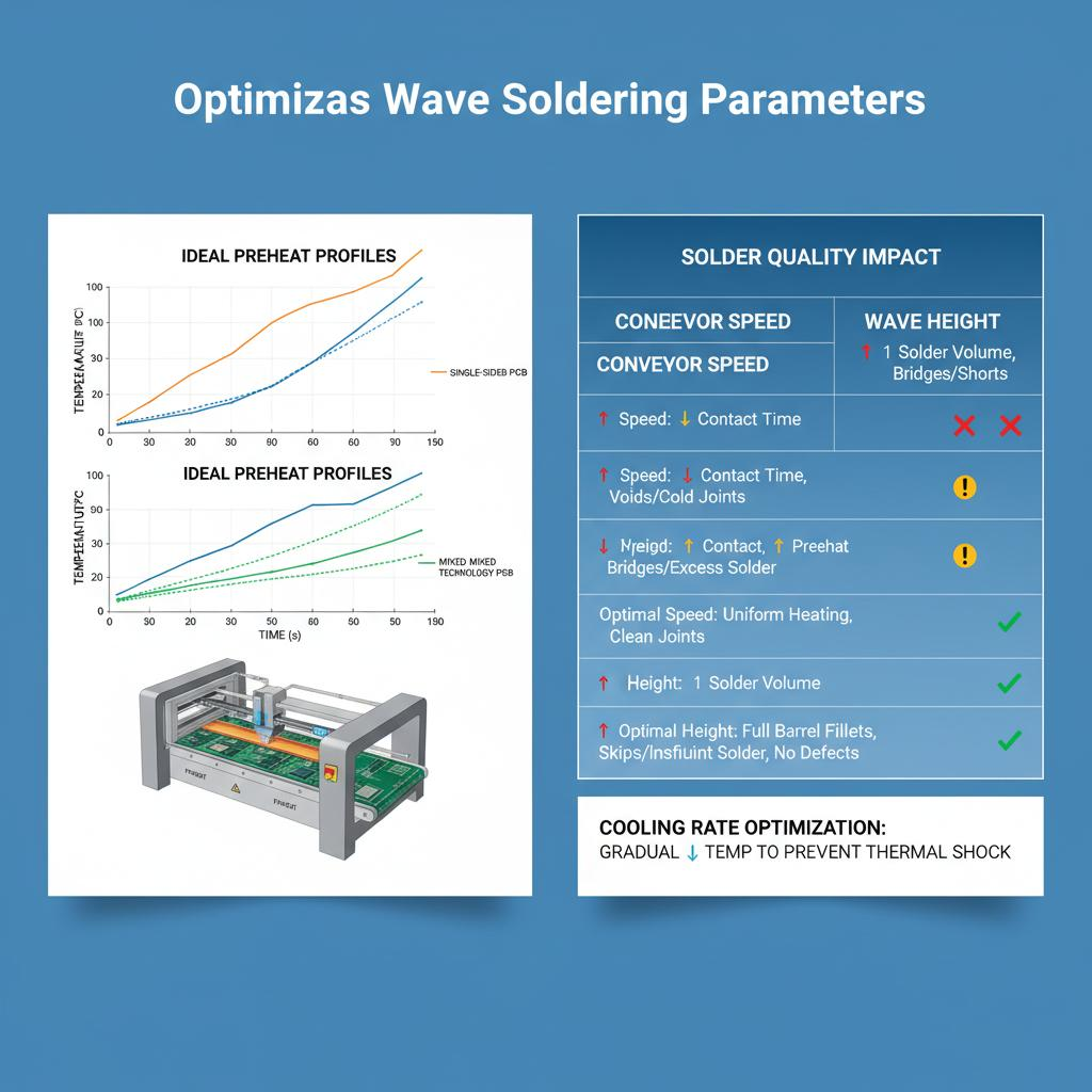
This graph clearly shows the difference in thermal profile required to handle different component types.
Pin-in-Paste (Intrusive Reflow) for Through-Hole Components
Engineers often want to eliminate the manual or wave soldering step for through-hole connectors.
● The Trick: Solder paste is printed over the through-holes. The component pin is inserted through the paste. During reflow, the paste melts and is wicked down into the hole by capillary action.
● Requirement: The paste volume has to specifically measure the filling of a hole up to IPC standards (Annular ring volume + Hole volume – Pin volume).