Why is JT different from other wave soldering manufacturers?
At JT, we believe we differ from other wave soldering manufacturers because our equipment is the best in the industry. We have been in business for over 25 years and know what it takes to produce high-quality equipment. Our team of experts constantly creates new and innovative products. As the best manufacturer, Shenzhen JT Automation Equipment Co., Ltd. is dedicated to providing the broadest range of top-quality tools and products.
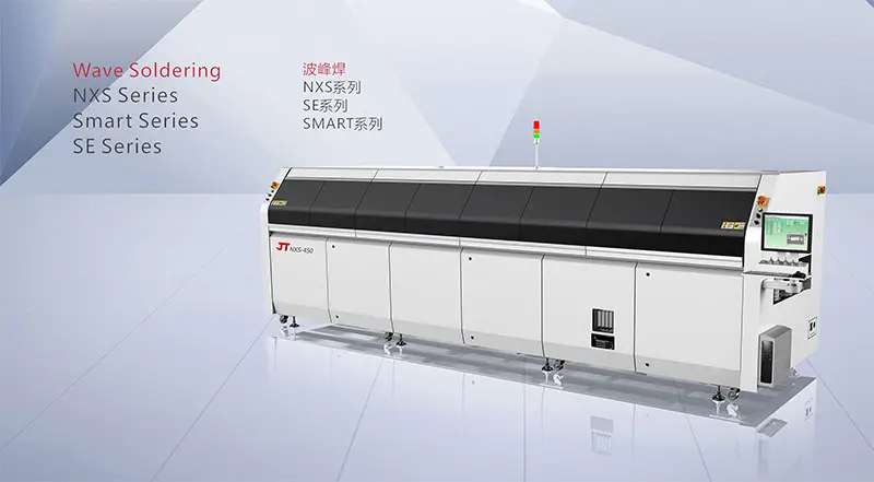
Let’s have a look at the details of Wave Soldering:
- About Wave Soldering
- Definition:
The PCB with the pieces is placed on the conveyor chain for the solder joint welding process at a specific angle and depth of immersion in the solder wave. This is done with the help of a pump that makes a solder wave on the liquid surface of the solder tank.
- Processes:
Simplification: Into the board ➡ Flux application ➡ Preheating ➡ Soldering ➡ Cooling
Detailed explanation: The circuit board travels via some flux coating equipment before entering the wave soldering machine via the conveyor finger. The flux is applied to the circuit board using ultrasonic, foam, or spray techniques. The board passes through a preheat zone before entering the solder pot and preheating after flux application gradually raises the temperature of the PCB and activates the flux. This is necessary because most fluxes have an activation temperature that must be reached and kept during soldering to ensure that the solder joint is completely wet.
This method allows the assembly to enter the wave crest with less thermal shock. If these things are not removed, they will boil and cause the solder to spatter when crossing the wave crest or produce vapor left inside the solder to produce hollow solder joints or sand holes. It can also be used to evaporate any moisture that may be absorbed or dilute the carrier solvent of the flux. Also, multilayer and double-sided boards need to be preheated at higher temperatures than single-sided boards because they can hold more heat.
The most popular wave soldering preheating techniques are forced hot air convection and infrared heating. Wave soldering devices utilize thermal radiation for this purpose. Forced hot air convection is the most efficient heat transfer method for wave soldering equipment in most procedures. After preheating, the board is soldered with either a single wave (-wave) or two waves (scrambled and -wave).
In the case of perforated components, one wave is adequate. Eddy currents form around the component pins because the solder flows in the opposite direction of the board’s path as it enters the wave. This works like a scrub brush to get the flux and oxide film residue off the top when the solder junction reaches the dipping temperature.
For hybrid technology assemblies, the scrambled wave is often employed first. As a result of this wave’s shorter width and increased vertical pressure, the solder can easily penetrate between the closely spaced pins and surface-mounted component (SMD) pads. The solder junction is finally completed by using the wave.
- The advantages of JT wave soldering
- Spray Module
- a. The preheating area is safer because flux can’t get in because of a separate spray module on the outside.
- b. Reduce the frequency of your wave soldering
- c. Structure optimization: Daily maintenance is simpler .
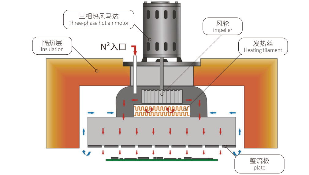
- 2. PreheatingModule
- a. The independent module is a preheating module that can be modified to meet the customer’s needs.
- b. Hot air preheating uses bare heating wire and an end riveting procedure to lengthen the life of the heating wire, enhance the preheating response time, and hasten the temperature recovery.
- c. Use infrared micro-short-wave spotlights that are low in energy consumption, have a high thermal penetration of the PCB, and have a power mode control response rate of about 4-6 s.
- 3. Compatible with the tin furnace module’s practical construction design:
- A structure for a quick-release nozzle based on an increase in adjustable nozzle level structure makes it easier to change the nozzle process.
- To alter the welding duration, the middle of the second wave can be moved back and forth between the trapezoidal wave’s width and height.
- Adjust the fence surrounding the nozzle to produce less tin slag.
- 4. Transmission:
- Cutting-edge chain assembling technique for rolling transport.
- Lowering the barrier to transport friction.
- An enhanced transmission
- Increased guide rail service life.
- A maximum load of 60 kg along the whole length of the track.
- Full V, full L, 2V+1L, and 3V+1L heavy-duty jaw configurations are freely customized
- Nitrogen system:
To fulfill the goal of inert protection, JT employs the patented nanotube gas dispersion technology at a lower nitrogen flow rate, which is much superior to the use of stainless-steel tube drilling technology for gas consumption and has huge inert protection effects.
- 6. Industry Support:
Savvy data management techniques (4.0).
If you have any queries regarding wave soldering, please let us know.