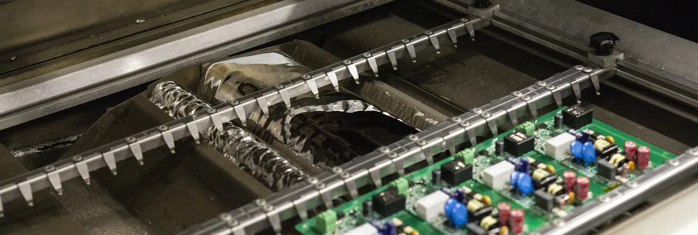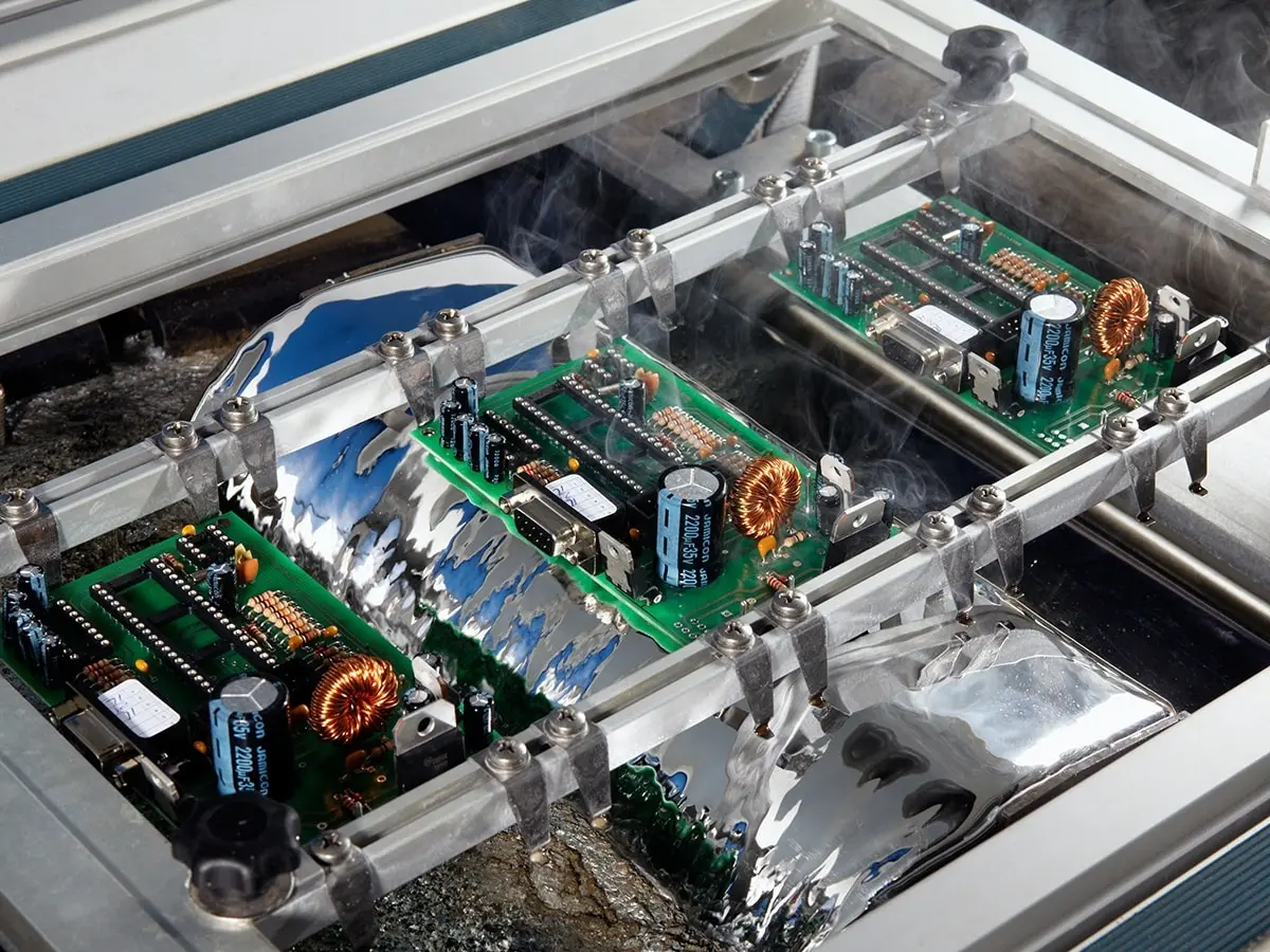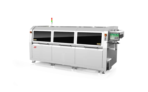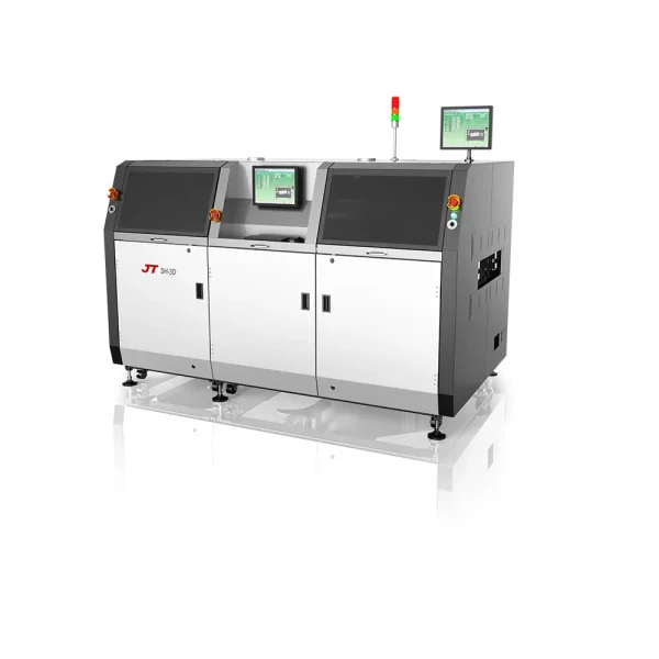

Through-hole (PTH) components are usually soldered to the PCB by wave soldering. However, here’s an alternative option – through-hole reflow soldering available for PCB assembly with PTH components.
Overview of Through-hole Reflow Soldering Technology
Through-hole reflow soldering, also called pin-in-paste reflow, is a PCB assembly technology that assembles the through-hole (PTH) components with the pick-and-place and reflow SMT (surface-mount technology) processes.
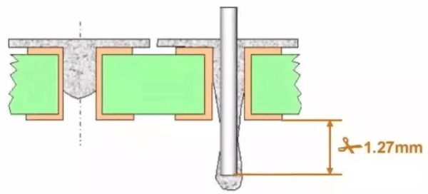
You can see the through-hole reflow or pin-in-paste assembly process below:
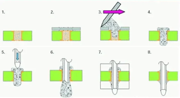
Step 1. Fabricate the PCB with plated-though holes.
Step 2. On the SMT line, transfer the PCB under the SMT stencil.
Steps 3-4. In the solder paste printing machine, the scraper pushes the solder paste through the SMT stencil holes to fill the PTH holes.
Steps 5-6. In the component pick-and-place machine, the PTH components with the SMDs are sucked by the nozzles to place on the PCB. If it cannot, after placing the SMD components, a technician will manually insert the leads of the PTH components through the PCB holes. Part of the solder paste will stick onto the PTH component leads, but most remain in the hole.
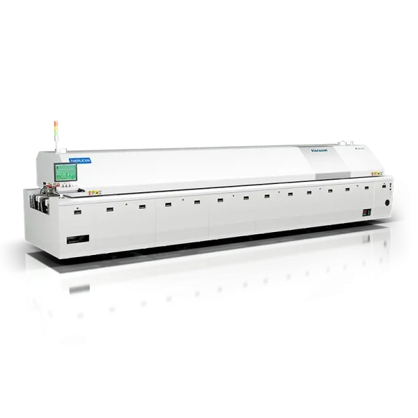
Steps 7-8. In the reflow soldering oven, all the SMDs and through-hole components are soldered tightly to the PCB. The solder paste in the hole and on the lead melts and forms the IMC (intermetallic compound) with the PCB copper wall and pad.
Through-hole reflow soldering provides reliable connections between the PTH component and the PCB board. It utilizes heat to melt solder paste applied to the leads of components.
Why do we use through-hole reflow soldering for electronics assembly? Cost reduction is the reason.
For PCB assembly projects, SMDs (surface-mount devices) account for about 80% of the component costs, but SMT assembly accounts for only 60% of the assembly fees; through-hole components account for about 20% of the component costs, but PTH assembly accounts for 40% of the assembly fees.
That’s why the project developers and electronic manufacturers consider through-hole reflow, as with it, all the PCB components can be mounted on only the SMT lines.
What to Take Care for PCB Though-hole Reflow?
Though pin-in-paste reflow saves big and is efficient, it has many requirements. You will need to consider the below aspects for through-hole reflow PCBs.
Solder paste filled in the PCB hole rate — The solder paste in the PTH hole should be at least 75%.
Standoff design — In PCB design for through-hole reflow, the PCB pads should be designed to accommodate the thermal and mechanical stresses during reflow, ensuring strong solder joints. Between the PTH component and its soldering pad, a standoff should be designed to increase the solder paste printing amount. What’s more, the standoff can prevent the solder beads between the PCB and the PTH component.
PTH component requirements — The PTH components for pin-in-paste reflow should be able to withstand the lead-free reflow soldering temperatures (260°C, 10 seconds). Besides, as the PTH components are picked and placed automatically, they had better be in the tape-on-reel package.
Via diameter — The PCB hole diameter should ensure the solder paste flows into the hole and the reliability of the assembly. It depends on the lead’s maximum diameter and effective diameter and the shape of the PTH component lead end.
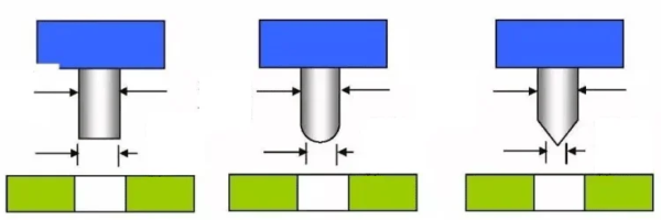
Flat-end lead: effective lead diameter = 100% maximum lead diameter
Round-end lead: effective lead diameter = 75% maximum lead diameter
Sharp-end lead: effective lead diameter = 50% maximum lead diameter
Reliability: For military and aerospace electronics that should withstand some mechanical strength, through-hole reflow had better not be used for PCB assembly as its reliability is not as good as wave soldering.