Comparison of MVC’s Reflow Soldering Capacity
MVC refers to the most vulnerable component (MVC) during reflow soldering, such as liquid dielectric aluminum electrolytic capacitors, connectors, DIP switches, LEDs, transformers, and PCB (printed circuit board) substrate materials. Lead-containing and lead-free components differ in their reflow soldering capacity.
• Lead Components
Since the peak temperature of reflow soldering does not exceed 230°C, the heat resistance of MVCs should be set at 240°C. This includes all soldering tools, equipment, and auxiliary materials manufactured by industrial manufacturers, all of which are designed and selected based on a 240°C heat resistance.
• Lead-Free Components
The peak temperature of lead-free reflow soldering can reach up to 250°C, therefore the minimum heat resistance of soldering materials must be at least 260°C. Therefore, all soldering tools, equipment, and auxiliary materials manufactured by industrial manufacturers must be designed and selected based on a 260°C heat resistance temperature.
Common Solder Paste Components for Reflow Soldering
• Reflow Soldering
Similar to wave soldering, reflow soldering uses the same common solder paste components: Sn37Pb eutectic solder paste and Sn36Pb2Ag solder paste.
• Lead-Free Reflow Soldering
The main solder paste alloy components used in lead-free reflow soldering include:
a. SAC305 solder paste. As one of the most widely used elements in modern industry, its melting point is 217°C to 220°C.
b. SAC387 solder paste. SAC387 is the eutectic composition of SnAgCu alloy, with a melting point of 217°C, at which the solid-liquid transition can be completed. Due to its lower melting point, it is mainly used in some special products, such as military applications.
Reflow Soldering Peak Temperature Range
• Reflow Soldering
For simple products, the peak temperature range during reflow soldering is 205°C to 220°C. However, for some complex products, such as some integrated circuit packages, the peak temperature can be as high as 225°C, as shown in the figure below.
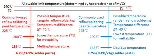
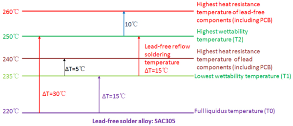
• Lead-Free Reflow Soldering
For lead-free reflow soldering, if the minimum peak temperature during actual reflow soldering is 235°C, the maximum peak temperature will depend on the temperature difference (ΔT) on the PCB board. ΔT, in turn, depends on the PCB size, thickness, number of layers, component layout, copper layer distribution, component size, and heat capacity. For larger, thicker PCBs with large, complex components, ΔT can typically be as high as 20°C to 25°C. Therefore, the peak temperature should be minimized to extend preheating and reflow soldering times, as shown in the figure below.
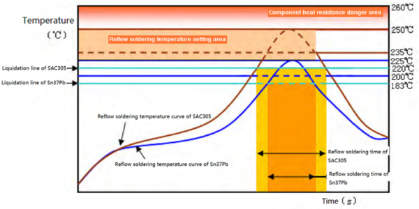
Reflow Soldering Time-Temperature Profiles
The following figure shows a comparison of the time-temperature profiles for leaded and lead-free reflow soldering.
Comparison of Self-Alignment Capabilities between Lead-Containing and Lead-Free Reflow Soldering
• Reflow Soldering
When using lead-containing solder paste (Sn37Pb, Sn36Pb2Ag) and PCB surface treatment (HASL Sn37Pb or OSP), self-alignment is well achieved if the deviation between the assembled components and the pads reaches 50%.
• Lead-Free Reflow Soldering
a. Due to the involvement of air in the reflow soldering process, SAC305 solder paste is used. The PCB pad surface treatment is ENIG and OSP, and SAC305 solder paste is used for the solder joints. Self-alignment is well achieved if the deviation between the assembled components and the pads is 25%.
b. Due to the involvement of nitrogen in the reflow soldering process, SAC305 solder paste is used. The PCB pad surface treatment is ENIG and OSP, and SAC305 solder paste is used for the solder joints. Self-alignment is also well achieved if the deviation between the assembled components and the pads is 50%.
Comparison of Lead Removal Processes for Lead-Containing and Lead-Free Solder Joints Rome wasn’t built in a day. The transition from a system using only tin-lead solder to a system using only lead-free solder cannot be completed in one step. A transition process is necessary that allows leaded and lead-free elements to coexist. This is because different sectors of the electronics manufacturing industry have not kept pace in their lead-free processes and technological readiness. Therefore, soldering defects are often difficult to avoid during this transition.
• Forward Compatibility
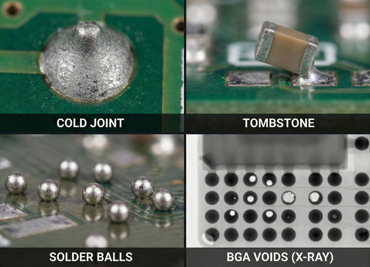
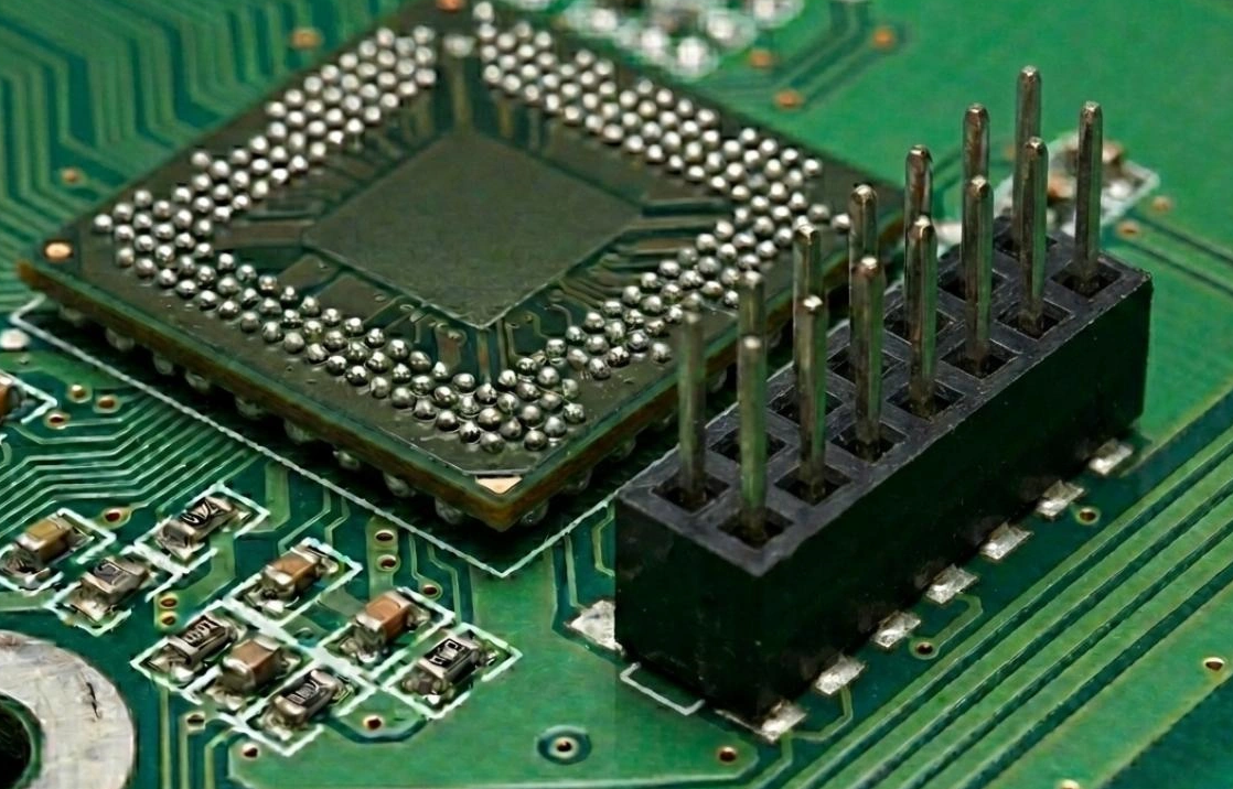
For example, when soldering leaded BGA (Ball Grid Array) joints using lead-free SAC solder paste, forward compatibility issues arise because component distributors’ lead-free processes lag behind those of PCB manufacturers. In this case, the BGA solder joint melts first and is covered by unmelted solder paste, causing significant collapse and oxidation of the leaded solder balls. As a result, voids and internal non-metallic inclusions are created because flux solvents and contaminants in the solder paste are difficult to remove, which is unacceptable.
• Backward Compatibility
Backward compatibility issues arise when lead-free solder needs to be used in conjunction with leaded solder paste. The solder paste (SnPb) applied to the pads melts before the SAC solder balls have melted. Lead diffuses to the boundaries of incompletely melted solder ball crystals. The extent of lead diffusion in SAC solder balls depends on the reflow temperature setting and the melting rate of SnPb solder in the solder paste. Therefore, solder joints become uneven and unstable.
To obtain higher quality and more reliable solder joints, the reflow time-temperature profile must be readjusted to ensure complete melting of the SAC solder balls and thorough mixing of lead in the SnPb solder paste with the molten SAC solder balls.
Comparison of Cooling Rates between Lead-Containing and Lead-Free Reflow Soldering Processes
• Reflow Soldering
Since the peak temperature of lead-containing reflow soldering is lower than that of lead-free reflow soldering, and the accumulated heat of the soldered components is not high, the cooling rate of the cooling unit can be maintained at 3 to 4°C/s.
• Lead-Free Reflow Soldering
Because the lead-free reflow soldering process has higher temperatures and accumulates more heat, accelerated cooling is necessary to prevent excessively long solder joint solidification time and grain thickening, which also suppresses segregation. Therefore, the cooling system of reflow soldering equipment should have a high cooling rate to quickly reduce the solder joint temperature. A cooling rate of 5–6 °C/s is typically required.
The Influence of Cooling Rate on Creep Resistance
• The Influence of Cooling Rate on Creep Resistance of Lead-Free Solder
a. Increased cooling rate enhances the creep resistance of the device because rapid cooling alters the microstructure. The fine dendrites formed by rapid cooling, as well as Ag3Sn particles in the substrate, enhance contact fracture resistance, thereby improving the creep resistance of the solder joint.
b. Slow cooling leads to crystal growth, which easily causes crack initiation and propagation. The improved creep resistance of SnAg is mainly attributed to the dispersion of reinforcing particles.
The Influence of Cooling Rate on Creep Resistance of Lead Solder
Unlike SAC alloys, lead exhibits a spherical shape during rapid cooling of lead eutectic solder, and all phases become refined with increasing cooling rate. However, the difference lies in the fact that lead has a lower hardness than the tin matrix, and in tin-silver alloys and SAC alloys, the lead content is higher than that of silver.