Optimizing the process of modern SMT (Surface Mount Technology) assembly lines involves multi-dimensional technological collaboration, requiring a closed-loop management system encompassing equipment configuration, parameter calibration, and quality inspection. This article focuses on the core need for improved production line efficiency, systematically outlining key criteria for equipment selection, such as the impact of pick-and-place machine accuracy and material supply system compatibility on capacity. It also emphasizes the refined tuning of process parameters, covering the scientific setting of core indicators such as solder paste printing thickness and reflow soldering temperature profiles. Regarding quality control, the article analyzes how the linkage mechanism between SPI (Solder In-Process Inspection) and AOI (Automated Optical Inspection) enables proactive defect interception and optimizes the placement process through data feedback. Furthermore, the article will use production line transformation case studies to quantitatively analyze the combined effects of equipment upgrades, process refactoring, and intelligent inspection technologies on improving defect rates and production efficiency.

Key Considerations for SMT Production Line Equipment Selection
Equipment selection is the first step in building an efficient SMT production line, requiring a comprehensive consideration of the balance between technical parameters, production needs, and cost-effectiveness. The selection of high-precision pick-and-place machines should focus on chip placement accuracy. Current mainstream equipment generally achieves a placement accuracy of ±0.025mm, meeting the placement requirements of 0201 micro-components. For printer configuration, the stability of the stencil positioning system and squeegee pressure control module is crucial, as these have a decisive impact on solder paste quality. During the production line layout planning phase, a modular design concept should be prioritized to ensure a closed-loop process flow between the printer, pick-and-place machine, and reflow soldering equipment, while reserving interfaces for SPI detection stations.
It is worth noting that equipment compatibility assessment should extend to the material supply system. A combination of dual-rail feeders and intelligent feeders can reduce changeover time by more than 40%. For multi-variety, small-batch production scenarios, it is recommended to choose an equipment architecture with rapid program switching capabilities. These systems typically integrate visual positioning compensation functions, effectively addressing the challenge of precise alignment for PCBs of different sizes.
Precise Adjustment of Surface Mount Technology (SMT) Process Parameters
The precise control of SMT process parameters directly affects component placement accuracy and production line stability. Squeegee pressure, printing speed, and solder paste release angle need to be dynamically adjusted according to the PCB material and pad size. For example, 0.1mm pitch BGA components typically require squeegee pressure controlled within the range of 3.5-4.2 N/mm², while high-density QFN packages require printing speeds reduced to below 30mm/s to ensure full solder paste filling. Simultaneously, the nozzle vacuum and placement height of the pick-and-place machin
Temperature control is another crucial dimension; the temperature profile of the reflow oven needs to be customized for the characteristics of different alloy solders. Typical lead-free processes require peak temperatures maintained between 235-245℃ for 40-60 seconds to balance soldering strength and component thermal stress. By introducing a real-time thermal imaging monitoring system, oven temperature fluctuations can be dynamically compensated, stabilizing the temperature deviation within ±1.5℃. Practice shows that the parameter tuning mechanism, combined with the equipment’s adaptive algorithm, can improve the chip placement yield to over 99.95%.
Practical Application of Intelligent Inspection Systems
After completing the chip placement process parameter debugging, the intelligent inspection system becomes the core line of defense for ensuring production quality. Modern SMT production lines integrate SPI (solder paste inspection), AOI (automatic optical inspection), and X-ray 3D imaging technologies to build a closed-loop inspection network throughout the entire process. The SPI system uses laser or raster projection technology to measure solder paste printing thickness, volume, and offset at the micrometer level, providing real-time feedback to the printer for parameter self-correction. AOI, on the other hand, uses high-resolution cameras and deep learning algorithms to accurately identify 12 common defects, such as component polarity misalignment and solder joint bridging, with a detection speed of up to 0.5 seconds per point.
More importantly, some advanced production lines have achieved deep integration of inspection data with the MES system, automatically optimizing equipment parameters through defect pattern analysis, forming an intelligent decision-making chain of “inspection-diagnosis-optimization.” A case study from an automotive electronics manufacturer shows that this system reduced the false positive rate by 65% while reducing manpower at inspection stations by 40%. This dynamic inspection mechanism lays the data foundation for subsequent collaborative inspection mechanisms between SPI and AOI.
SPI and AOI Collaborative Inspection Mechanism
In the SMT assembly process, the quality of solder paste printing and component placement accuracy directly affect the final yield. SPI (Solder Paste Inspection System) uses 3D imaging technology to fully inspect the thickness, volume, and distribution of solder paste, identifying potential defects such as printing misalignment and bridging in advance, intercepting defects before reflow soldering. AOI (Automated Optical Inspection System) performs multi-dimensional analysis of component polarity, offset, and soldering morphology after placement, with its high-speed image processing capabilities covering the precision inspection needs of components with a 0.4mm pitch.
Through equipment data interconnection, an SPI-AOI collaborative mechanism is constructed, enabling dynamic calibration of inspection results and a closed-loop defect traceability: SPI inspection data is synchronized to the AOI system in real time, optimizing the coordinate compensation parameters of the placement machine; soldering anomalies reported by AOI trigger reverse adjustments to the SPI inspection threshold, forming a two-way quality early warning network. This collaborative mode improves the defect interception efficiency of key processes by 40% and drives process data utilization to exceed 85%, providing technical support for reducing the defect rate to below 0.1%.
Core Analysis of Surface Mount Technology
The core of surface mount technology (SMT) lies in achieving automated assembly of high-density, high-precision components. Its process chain is based on three main pillars: solder paste printing, component placement, and reflow soldering. The quality of solder paste printing directly affects the accuracy of subsequent placement, requiring optimization of the stencil aperture design and dynamic adjustment of printing pressure to ensure that the solder paste deposition thickness is controlled within an error range of ±10μm.
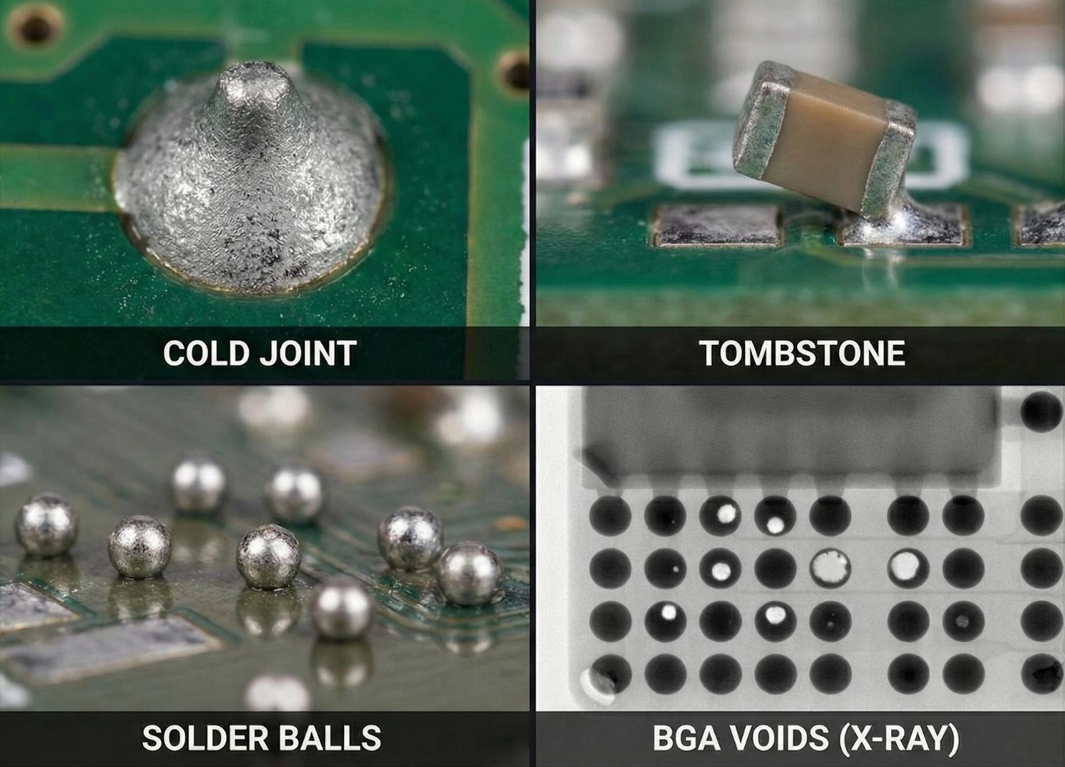
The core of the placement process lies in the equipment positioning accuracy and nozzle compatibility. By selecting a pick-and-place machine with a CPK (process capability index) ≥1.33, a stable performance of 0201 component placement offset ≤30μm can be achieved. Reflow soldering relies on precise temperature profile design. A typical eight-zone oven needs to control the peak temperature within the range of 235-245℃ and maintain a liquid phase residence time of 60-90 seconds to eliminate cold solder joints and tombstoning defects. The synergistic optimization of these key technologies lays the physical foundation for the effective performance of the SPI/AOI inspection system.
30% Production Line Efficiency Improvement Solution
In optimizing the efficiency of SMT placement production lines, equipment collaboration and process reengineering constitute the core driving forces. By introducing a modular production line design, dynamic matching of pick-and-place machines, reflow ovens, and loading/unloading units can be achieved, reducing equipment idle time to below 8%. Production cycle optimization requires considering component specification differences and adopting a tiered feeding strategy, reducing feeder changeover frequency by up to 40%.
Simultaneously, deploying an intelligent scheduling system to perform deep learning on order data automatically generates optimal placement paths, shortening single-board placement cycles by 12%-18%. Furthermore, the parallel layout of SPI and AOI inspection stations can compress quality verification time by 30%, while the MES system’s real-time monitoring and early warning of equipment status further reduces unplanned downtime. Practice shows that through multi-dimensional parameter linkage control, the overall production line efficiency improvement can consistently exceed the 30% threshold.
Component Placement Defect Rate Control Method
In the SMT placement production process, controlling the component placement defect rate requires multi-dimensional collaborative optimization. First, the integrated application of SPI (Solder Solder Paste Inspection System) and AOI (Automated Optical Inspection System) is the core approach. SPI precisely measures the thickness and shape of the solder paste through 3D scanning, ensuring a quality benchmark during the printing stage; AOI performs high-speed image comparison after placement to detect defects such as component misalignment and reverse polarity.
Second, dynamic calibration of process parameters is equally crucial, including precise matching of the pick-and-place machine nozzle vacuum, placement pressure, and speed, which can reduce component damage caused by mechanical stress. Experimental data shows that when the solder paste printing thickness tolerance is controlled within ±10μm and the placement pressure gradient adjustment accuracy reaches 0.05N, the component displacement rate can be reduced by more than 60%. Furthermore, establishing a real-time data feedback mechanism, directly linking abnormal signals from the inspection system to the equipment parameter correction module, enables closed-loop control of defects, ultimately stabilizing the overall defect rate within the 0.1% threshold.
In-depth Analysis of Production Line Transformation Strategies
After completing equipment selection and parameter debugging, the implementation of production line transformation strategies becomes a key node for efficiency breakthroughs. Specifically, the approach needs to focus on three aspects: equipment layout optimization, process flow restructuring, and data system integration. Modular production line design can shorten material turnaround distances and enable parallel operations; simultaneously, introducing dynamic balancing algorithms allows for real-time adjustment of the matching rhythm between pick-and-place machines and reflow soldering equipment, reducing equipment idle time.
At the process flow level, standardized operating procedures (SOPs) and SPC process control technology are employed to ensure the stability of key processes such as solder paste printing and component placement. Furthermore, the data traceability function based on the MES system can accurately locate bottleneck workstations and generate optimization suggestions. For example, one EMS company, by integrating SPI and AOI inspection data streams, reduced the process parameter iteration cycle from 72 hours to 8 hours, improving placement accuracy by 15%. Building on this, production line modifications must also consider flexible production capabilities, reserving equipment expansion interfaces to adapt to multi-variety production needs.
Conclusion: Through systematic equipment selection optimization, precise process parameter tuning, and integration of intelligent detection technologies, the path to improving the overall efficiency of SMT (Surface Mount Technology) production lines has gradually become clear. Scientific matching of equipment configuration and production line design can significantly reduce redundant energy consumption. The application of SPI (In-Site Detection) and AOI (Automated Optical Inspection) collaborative detection mechanisms not only achieves full-process monitoring of solder paste printing and component placement but also moves defect interception points forward, effectively reducing subsequent rework costs.
Dynamic optimization of process parameters requires combining material characteristics and equipment performance, establishing standardized operating windows through data modeling and real-time feedback. It is worth noting that improving production line efficiency does not solely rely on technological upgrades; it also requires a continuous improvement loop formed through process reengineering and standardized personnel operations. With the deepening application of Industrial Internet of Things (IIoT) technology, the intelligent iteration of future SMT production lines will further extend towards predictive maintenance and adaptive control.