Section 1: How Traditional Reflow Ovens Work
The so-called reflow soldering process, also known as the reflow process, literally translates to reflow soldering or reflow soldering technology. Its basic operating principle is that a PCB, printed solder paste, and mounted components enter a reflow oven and are slowly transported by rails into the furnace chamber, where they are heated both above and below. Early heat was generated by infrared radiation, but nowadays, hot air is primarily blown into the furnace chamber to heat the PCB, solder paste, and components. The hot air entering the furnace chamber is driven by a blower (a motor) and then passes through a heater (a wire) where it is heated to form hot air. The temperature of the hot air is set by the process technician.
A temperature sensor is installed at the furnace outlet to monitor the hot air temperature in real time and transmit the monitoring results to the main control computer, which adjusts the current and power of the heater to achieve the ideal hot air temperature. The hot air entering the furnace chamber transfers heat to the components, PCB, and solder paste. As the product moves forward, its temperature increases, eventually reaching the melting point of the solder paste. The solder paste and tin powder particles melt and wet the component soldering end and the PCB pad, forming a solder joint. The product then enters the cooling zone, where cold air is blown into the furnace to cool the product. Once the solder solidifies, it is discharged from the furnace, completing the soldering process.
Section 2: Current Status and Application of Advanced Reflow Oven Technology
Traditional nitrogen and air furnaces are mature and widely used in the industry. However, with the increasing demand for high-reliability products, traditional reflow ovens are increasingly unable to meet these demands. Consequently, the industry has developed alternative soldering equipment to meet these evolving needs.
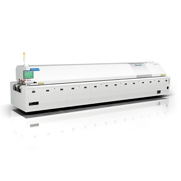
Vacuum Reflow Oven, Vacuum Vapor Phase Soldering
As we all know, during soldering, as the solder melts, gases trapped within the solder joint become trapped within the solder, forming bubbles. The presence of bubbles affects solder joint strength, hinders high-frequency signal transmission, and ultimately affects product reliability. To achieve low-bubble solder joints, vacuuming the solder melt is an effective method. This is why vacuum reflow ovens were developed. The operating mechanism of vacuum reflow ovens is shown in the figure below. Vacuum reflow ovens divide the equipment track from a single unit into three sections. For example, in a ten-zone reflow oven, zones 1 to 3 are the heating zone, zones 4 to 7 are the equalizing zone, zones 8 and 9 are the solder melting zone, and zone 10 is vacuumed to remove bubbles from the solder joint before entering the cooling zone. Temperature zones 1 to 9 form the first track section, zone 10 is a separate track section, and the cooling zone and exit section form the third track section.
After more than a decade of development, vacuum reflow soldering has matured. The vacuum zone has evolved from pure heat preservation vacuuming to infrared heating vacuuming. The impact on product IMC formation and temperature curve adjustment has become essentially negligible. It is expected that vacuum reflow soldering will be increasingly widely used in more high-end products in the future.


When evaluating vacuum reflow soldering equipment, the following considerations should be taken: track deformation and board jamming; vacuum extraction stage selection; vacuum chamber heating capacity; overall vacuum zone cycle time (double-gauge equipment is generally recommended); and vacuum tightness.
Some medical and communications components are not heat-resistant, requiring soldering under limited temperature conditions. This has led to the development of vapor phase soldering. The basic principle of vapor phase soldering is to select a liquid with a suitable fixed boiling point, heat it, and vaporize it. The vaporized liquid then heats the product within the cavity. The cooled gas then turns back into liquid and collects at the bottom, where it is heated again and vaporized. This process is repeated until the solder melts and forms a joint. To reduce bubbles in the joint, a vacuum is applied during the final stage of vapor phase soldering, creating a vacuum vapor phase soldering process.
Formic Acid Furnace, Nitrogen-Hydrogen Furnace
In the IC packaging soldering process, solder joints are very small. For example, flip-chip solder joints are only about 30µm in size. These tiny solder joints must be cleaned before packaging. However, cleaning micro-gap solder joints is difficult, costly, and environmentally unfriendly. This necessitates the use of flux in the IC packaging process. However, without flux, the oxide layer at the soldering interface cannot be removed, affecting soldering quality. Nitrogen-hydrogen furnaces, formic acid furnaces, and acetic acid furnaces can effectively address this problem.

This type of welding equipment operates without flux. The product to be welded is placed in the furnace, which is then closed and evacuated. During heating, nitrogen and hydrogen are then introduced into the furnace, acting as reducing agents to remove the oxide layer at the weld interface. After welding, the product can be moved to the next process without cleaning. This type of equipment is widely used in the IC packaging industry and has recently gained widespread adoption in IGBT sintering in mainland China.
Sintering Furnaces
Sintering processes have long been used in the automotive electronics industry. Early sintering processes used copper and silver pastes, and post-sintering cleaning was still required.
Vertical Furnaces
Vertical furnaces are widely used in adhesive curing. Their basic operating principle is continuous in-line production of products, such as in the underfill process. After underfilling, the product, along with the adhesive, enters the vertical furnace. With each entry, the track rises. When the product reaches the top, it is transferred to the other side, then descends one level at a time until it reaches the track level, and finally is conveyed out. This large “X”-shaped structure allows for extended product heating time within the furnace, up to two hours, while occupying minimal floor space. This eliminates the need for batch-by-batch baking for underfill, potting, and sealant curing processes, saving labor, material resources, and factory space. Vertical furnaces are becoming increasingly popular in today’s industries.

Tunnel Ovens
For large-scale potting products, such as white goods, where curing times are long and the product occupies a large space, tunnel ovens are a cost-effective solution for improving curing efficiency and reducing the space required. The basic working principle of a tunnel oven is to store the product on a substrate trolley, which then enters the oven chamber for curing. This allows for continuous production while significantly reducing space requirements.
Section 3: Specialized Welding Technologies in the Industry
Market demand is the driving force behind technological development. Traditional welding techniques, in addition to those described in this article, include laser welding, micro-flame welding, fusion welding, resistance welding, ultrasonic hot pressing, drop welding, group welding (multi-spot welding), mini welding, selective welding, and robotic welding. I will introduce each of these techniques to colleagues when the opportunity arises.